Ghost Phone restoration complete!
So, I got the replacement single-line 20Hz ringer from Oldphoneworks, who I highly recommend if you’re into old phones and parts thereof.
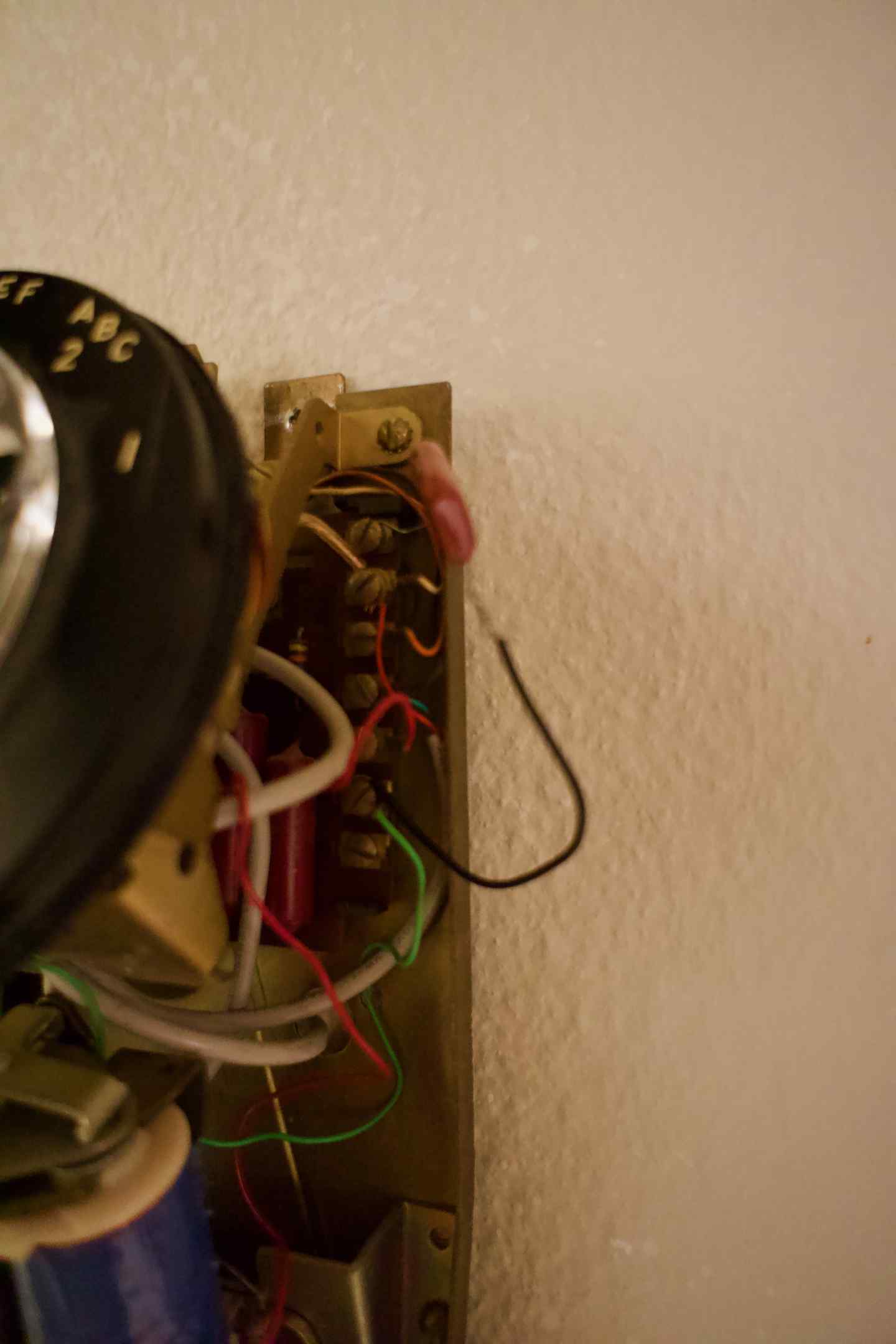
Out of the box it didn’t work, but the old ringer had a large-ish (.2µF) capacitor that was wired in, and after poring over some old wiring diagrams and poking at it with a multimeter it seemed pretty likely that I needed a capacitor for this new setup. The original capacitor was wired across two terminals, one of which was the negative pin of the ringer coil, and when I measured the voltage difference between those two terminals it had around 40V of DC and then while ringing it would get another 50V-ish of AC, with no voltage difference across the two terminals of the ringer coil.
Just wiring a wire where the capacitor was didn’t work generated a tiny (concerning) spark, and didn’t actually cause the ringer to ring.
So, I reached out to Matt at Oldphoneworks, and he immediately got back to me saying that the phone he pulled it from had a capacitor built-in to the telephone network, and suggested wiring a capacitor in series with the ringer coil and trying the capacitor that was on my existing ringer; he didn’t know what the capacitor’s value was but suggested that 1µF would be appropriate.
Wiring it in series didn’t make much sense to me given the voltages I measured, and it wasn’t particularly easy to use the previous ringer’s capacitor (because even after removing it from the ringer’s mount, the crimp connectors wouldn’t fit through the thru-holes, so obviously they were crimped on after the wires had been routed through), but I tried bodging it in rather precariously. Doing it in series with the 20Hz ring coil didn’t work (as I expected), but wiring it up where it was previously did cause the clapper to vibrate weakly.
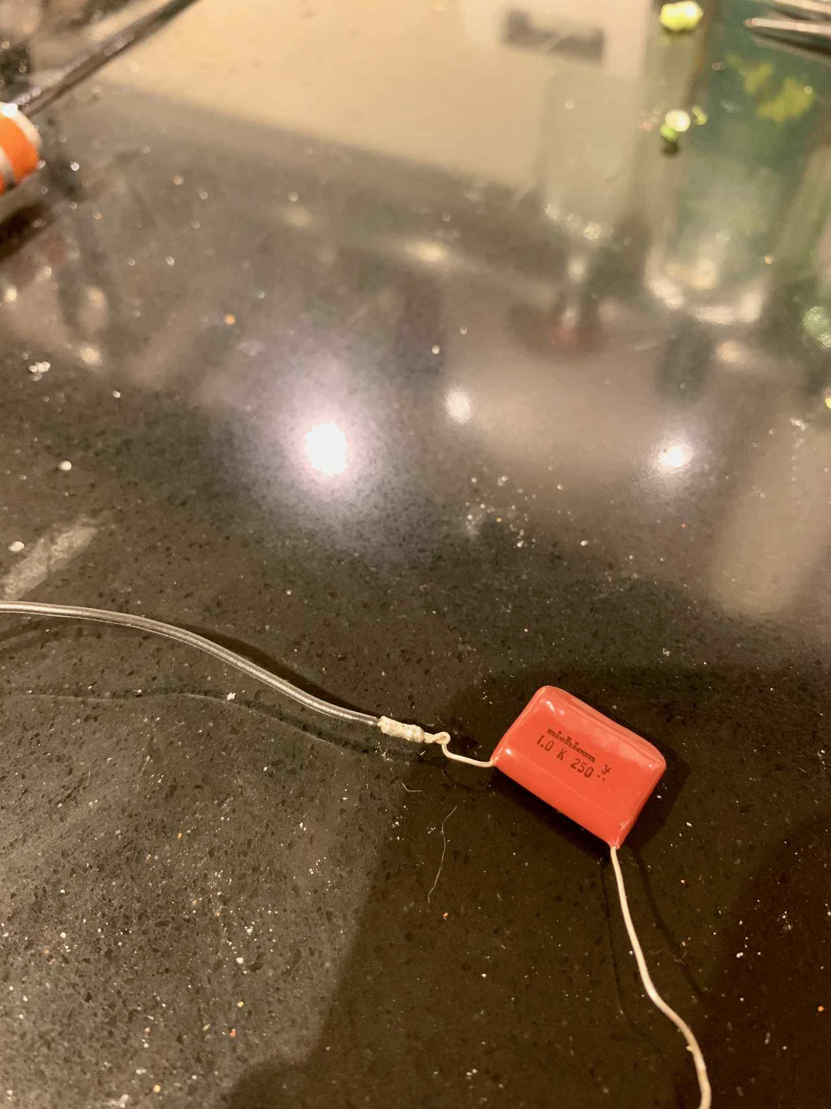
So I ordered some 1µF capacitors on eBay.
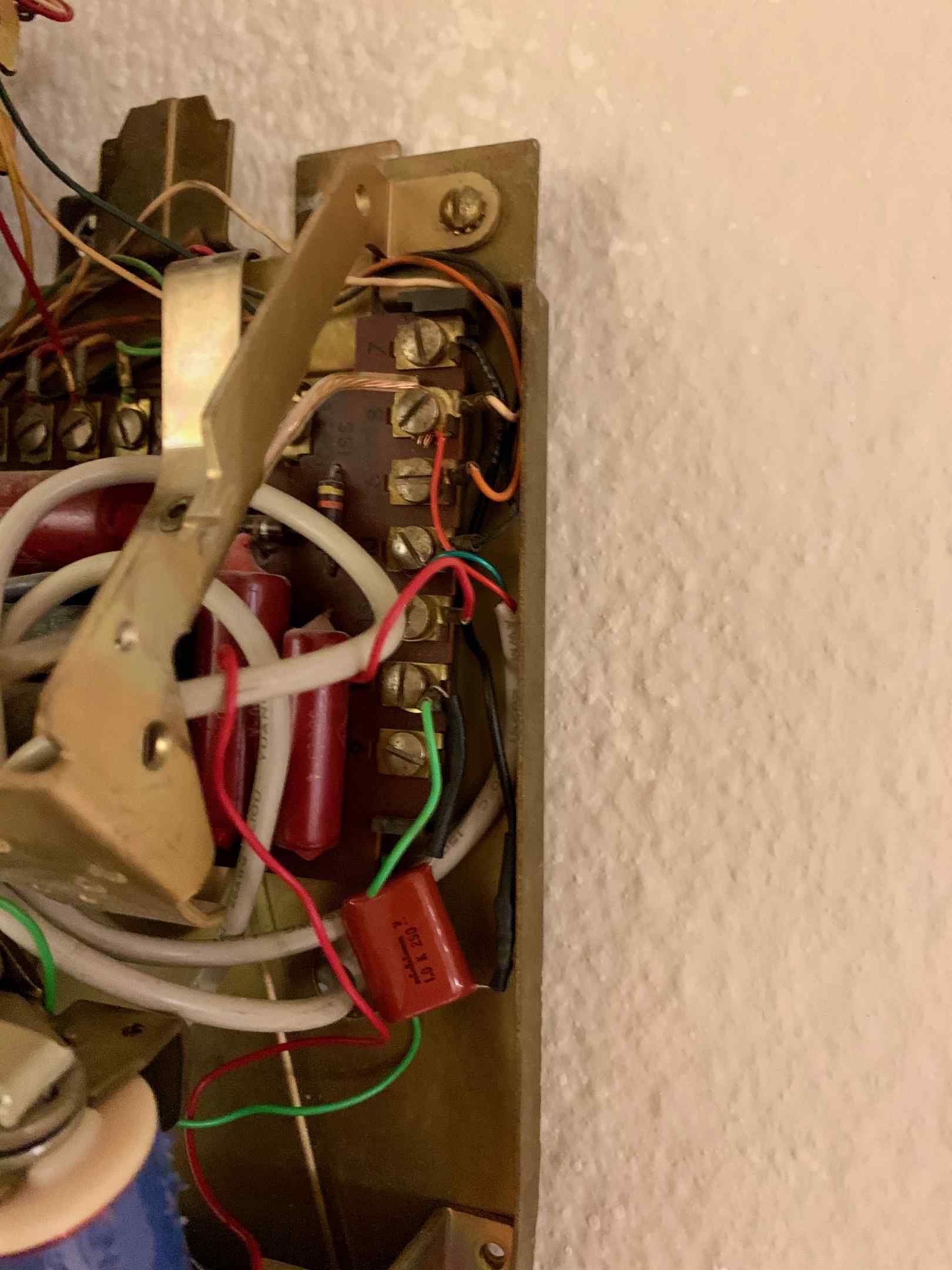
They arrived today, and I wired one up based on where the old 0.2µF capacitor went, and now the ringer works perfectly (after adjusting the clapper tension and bell positions, anyway, which was a lot easier than I expected and quite satisfying).
So this phone can now do incoming rings and outgoing calls via pulse dialing on the Grandstream HT502!
It would have been way easier (and probably cheaper overall) to just get a different Grandstream device that supported both pulse dialing and configurable ring frequency, but that would have felt like a partial solution. Now I have a fully-refurbished old phone that works on any modern pulse-dialing system. I also have a spare 30Hz party line ringer.
The actual ringer mechanism is a bit different than the 30Hz ringer’s, and it makes it somewhat more forgiving with setup. The 30Hz ringer was designed with a rigid bar that was supposed to barely hit against the bells through its full range of natural motion. The 20Hz ringer, on the other hand, doesn’t move all the way between the bells, but instead the clapper arm is a bit of spring steel that is intended to overshoot and spring back. This is a better (and probably newer!) mechanism because it doesn’t require as much precision with the bell positioning; the bell just needs to be closer than how far the spring makes it overshoot.
I was actually worried that the ringer still wouldn’t work because I had thought the arm was rigid, and there was no way to adjust the coil tension such that it would reach the bells through its full range of motion, but fortunately as soon as I tested it, it became obvious how it was supposed to work.
Anyway, now whenever people see the phone and ask if it works I can tell them, “Call the number and see!”
Also it’s another way for spammers to call me! Hooray!
Comments
Before commenting, please read the comment policy.
Avatars provided via Libravatar